| Location
| Thread | Tightening Torque Nm (ftlb) |
| Crankcase Girdle (studs)
| M 12 x 1.5
| 1st. Stage 30 (22) |
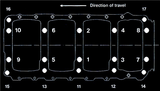
| Girdle Torque Sequence Diagram
|
| 2nd Stage 60º degree turning angle (or 65 Ft.Lb)
|
|
| M 10
| 1st Stage 20 (15) |
|
|
| 2nd Stage 50 (37) |
|
| M 8
| 20 (15)
|
|
| M 6
| 10 (7)
|
| Balance Shaft Cover
| M 6
| 10 (7) secured with Loctite 270
|
| Cover for balance shaft housing to top
section of crankcase
|
|
|
| Attachment of bearing casing left and right to
top section of crankcase
| M 8
| 20 (15)
|
| Connection Rod Nut
| M 10 x 1.25
| 75 + 5 (55 + 4)
|
| Coolant Drain Screw in Block crankcase
| M 8
| 20 (15)
|
| Oil Pan to Crankcase
| M 6
| 1st stage hand-tight
|
|
|
| 2nd stage 4 (3)
|
|
|
| 3rd stage 10 (7)
|
| Oil Pan Insert to Pan
| M 5
| 6 (4) secured with Loctite 270
|
| Oil Drain Plug
| M 20 x 15
| 50 (37)
|
| Engine Support L&R to Crankcase
| M 10
| 48 (35)
|
| Flywheel to Crankshaft
| M 10 x 1.25
| 1st stage 40(29)
|
|
|
| 2nd stage 90(66)
|
| Sensor Bracket to Crankcase
| M 8
| 20 (15)
|
| Front Crank Bolt
| M 16 x 1.5
| 210 (155)
|
| Sensor to Bracket
| M 6
| 8(6)
|
| Belt pulley to gear wheel
| M 6
| 8(6)
|
| Intake Manifold Bolts to Head
| M 8
| 20(15)
|
| Hollow Screw for Vacuum on Intake
| M 8 x 1
| 10(7)
|
| Attachment of Connector for Coolant Pipe
| M 8
| 20(15)
|
| Connection of fitting for heater flow line to cylinder head
| M 8
| 20(15)
|
| Camshaft Gear Wheel Bolt | M 10
| 65-7(48-52)
|
| Bracket to camshaft bearing
| M 6
| 8(6)
|
| Connection piece to driver
| M 5
| 5(4)
|
| Rear Cam Cover w/Hoisting Bracket
| M 6
| 8(6)
|
| Distributor finger to connection piece
| M 4
| 4(3)
|
| Gear Wheel to Balance Shaft
| M 10
| 45(33)
|
| Tensioning Roller to Bearing Housing
| M 10
| 45(33)
|
| Roller to Bearing Bearing Housing Right
| M 10
| 45(33) secured with Loctite 270
|
| Water Pump to Crankcase
| M 6
| 8(6) Secured with Loctite 270
|
| Roller to Water Pump Housing
| M 10
| 45(33)
|
| Oil Pump to Crankcase
| M 6
| 8(6)
|
|
| M 10
| 45(33)
|
| Tensioning Roller to Oil Pump Housing
| M 10
| 45(33)
|
| Belt Cover
| M 6
| 8(6)
|
| Spark Plugs
| M 14 x 1.25
| 25-30(18-22)
|
| Alternator Bracket to Crankcase
| M 10
| 45(33)
|
| Screw Nut to Catalytic Converter
| M 14 x 1.5
| 30(22)
|
| Temperature Sensor
| M 12 x 1.5
| 15(11)
|
| Oil Pressure Sensor
| M 18 x 1.5
| 35(26)
|
| Diaphragm Damper & Pressure Regulator to Fuel Rail
| M 16 x 1.5
| 30(22)
|
| Cap Nut to Fuel Rail
| M 12 x 1.5
| 12(9)
|
| Housing Insert in Oil Pump Housing
| M 6
| 8 (6) Mating face sealed with Loctite 574
|
| Radiator Housing / Thermostat Housing to Crankcase
| M 8
| 20 (15)
|
| Screw plug to oil / water radiator housing
| M 18 x 15
| 35 (26)
|
| Coolant Vent Screw
| M 8 x 1
| 12 + 3 (9 + 2)
|
| Oil Pressure Relief Valve
| M 20 x 1.5
| 45 (33)
|
|
|
| 20 (15)
|
| Air Oil Separator (AOS) to Crankcase
| M 8
| 20 (15)
|
| All other bolts and nuts:
| M 6
| 8 + 2 (6 + 1)
|
|
| M 8
| 20 + 2 (15 + 1)
|
|
| M 10
| 40 + 5 (29 + 4)
|
| Location
| Thread | Tightening Torque Nm (ftlb) |
| Cylinder head to upper section of crankcase
| Refer to tightening instructions for cylinder head
|
|
| Camshaft housing to cylinder head
| M8
| 20 (15)
|
| Aluminum screw plugs to camshaft housing
| M 18 x 1.5
| 40 (29)
|
| Camshaft bearings to camshaft housing
| M 6
| 8 (6)
|
| Knocking sensor
| M 8
| 9 (7), from Mod.'88 20
|
| Hollow screw / oil line to balance shaft cover
| M 14
| 25 + 3 (18 + 2)
|
| Hollow screw / oil return line to oil pan
| M 26 x 1.5
| 75 + 5 (55 + 4)
|
| Hollow screw / coolant line to turbocharger
| M 16 x 1.5
| 35 + 5 (26 + 4)
|
| Connection piece to turbocharger
| M 16 x 1.5
| 35 + 5 (26 + 4)
|
| Securing union nut / coolant line to turbocharger
| M 22 x 1.5
| 35 + 5 (26 + 4)
|
| Location
| Thread | Tightening Torque Nm (ftlb) |
| Control arm to cross member
| M 12 x 1.5
| 65 (48)
|
| Control arm to body
| M 10
| 46 (34)
|
| Control arm bearing to alum. control arm (caster eccentric)
| M 12 x 1.5
| 85 (63)
|
| Control arm to steering knuckle
| M 10
| 50 (37)
|
| Cross member to body
| M 12
| 85 (63)
|
| Heat sink for hydraulic bearing to cross member
| M6
| 10 (7)
|
| Track rod to steering knuckle
| M 12 x 1.5
| Castle nut 30 + 20 (22 + 15)
|
|
|
| Locking nut 50 (37)
|
| Stabilizer suspension to body
| M 8
| 23 (17)
|
| Clip for stabilizer to suspension
| M 8
| 23 (17)
|
| Stabilizer suspension to control arm
| M 10
| 25 (18)
|
| Plug for vibration damper insert
|
| 150 +/- 30 (111 +/- 22)
|
| McPherson strut bearing to shock absorber strut
| M 14 x 1.5
| 77 (57)
|
| Fillister head screw to clamping nut
| M 7
| 13 + 3 (10 + 2)
|
| Cover plate to steering knuckle
| M 7
| 10 (7)
|
| Brake caliper to steering knuckle
| M 12 x 1.5
| 85 (63)
|
| McPherson strut to steering knuckle
| M 12 x 1.5
| 100 (74)
|
| McPherson strut to body
| M 8
| 25 (18)
|
| Air deflector to McPherson strut
| M 6
| 10 (7)
|
| Brake disk to wheel hub
| M 8
| 23 (17)
|
|
| M 6
| 10 (7)
|
| Light - alloy wheel to brake disk
| M 14 x 1.5
| 130 (96)
|
| Location
| Thread | Tightening Torque Nm (ftlb) |
| Universal shaft to steering gear and steering shaft
| M 8
| 30 + 5 (22 + 4)
|
| Steering gear to cross member
| M 8
| 23 (17)
|
| Cover for pinion bearing
| M 6
| 7 (5)
|
| Cover on press. piece bearing
| M 6
| 7 (5)
|
| Check nut for adjustment bolt
| M 10 x 1
| 25 (18)
|
| Track rod to steering knuckle
| M 12 x 1.5
| Castle nut 30 + 20 (22 + 15)
|
|
|
| Locking nut 50 (37)
|
| Track rod to steering rack (not for power steering)
| M 22 x 1.5
| 50 (37)
|
| Track rod joint to track rod (not for power steering)
| M 14 x 1.5
| 30 (22)
|
| Steering wheel to steering shaft
| M 16 x 1.5
| 45 (33)
|
| Steering column switch to jacket tube
| M 8
| 15 (11)
|
|
| M 5
| 4 (3)
|
| Jacket tube to body
| M 8
| 23 (17)
|
| Support bearing to body
| M 6
| 7 (5)
|
| Power steering
| Values are the same as models w/o power steering
| Values are the same as models w/o power steering
|
| Track rod to steering rack
| M 14 x 1.5
| 70 (52)
|
| Track rod joint to track rod
| M 14 x 1.5
| 70 (52)
|
| Pressure and return line to steering gear
| M 12 x 1.5
| 20 (15)
|
| Pressure line to servo pump
| M 14 x 1.5
| 30 (22)
|
| Ring hose nipple for suction hose to servo pump
| M 16 x 1.5
| 45 (33)
|
| Location
| Thread | Tightening Torque Nm (ftlb) |
| Bearing flange to transv. tube
| M 10
| 46 (34)
|
| Bearing flange to body
| M 12 x 1.5
| 70 (52)
|
| Thrust bearing to bearing flange
| M 10
| 46 (34)
|
| Thrust bearing to body
| M 10
| 46 (34)
|
| Support bearing to body
| M 10
| 46 (34)
|
| Support bearing to strut
| M 8
| 23 (17)
|
| Axle control arm to rear axle strut (locking nut camber eccentric)
| M 12 x 1.5
| 90 (66)
|
| Axle control arm to rear axle strut (locking nut)
| M 12 x 1.5
| 103 (76)
|
| Axle control arm to transverse tube
| M 12 x 1.5
| 61 (45)
|
| Vibration damper to body
| M 12 x 1.5
| 61 (45)
|
| Vibration damper to aluminum control arm
| M 14 x 1.5
| 123 (91)
|
| Adjusting lever to spring strut
| M 16 x1.5
| 245 (81)
|
| Stabilizer suspension to rear axle strut and stabilizer
| M 10
| 46 (34)
|
| Stabilizer fastening clip to rear axle transverse tube
| M 8
| 23 (17)
|
| Wheel hub to rear wheel shaft with aluminum control arm
| M 22 x 1.5
| 500 (369)
|
| Universal shaft to transmission and rear wheel shaft
| M 8
| 42 (31)
|
| Cover plate to axle control arm
| M 6
| 10 (7)
|
| Brake caliper to axle control arm
| M 12 x 1.5
| 85 (63)
|
| Brake line to brake caliper and brake hose
| M 10 x 1
| 12 (9)
|
| Mounting bracket for brake line to brake carrier or axle control arm
| M 6
| 10 (7)
|
| Cable holder to control arm
| M 6
| 10 (7)
|
| Brake disk to wheel hub
| M 6
| 5 (4)
|
| Light-alloy wheel to wheel hub
| M 14 x 1.5
| 130 (96)
|


