WIRING OF MAF METER HARNESSIn the following instruction, we are installing a MAF Meter Harness for our Mass Air Flow Kits into the 944 Turbo harness.This factory wiring harness happens to be out of the car. Many of you would be installing this meter harness harness with the factory wiring harness still in the car. All steps would be the same. You just do your work under the hood. It is not necessary to remove the factory harness and we advise against it unless you're pulling the engine at the same time. Step #1 "Cut Plug & Ready Connections"Although not shown, we need to cut off the old plug that attached to the AFM (Air Flow Meter). We suggest you make this cut about 3 inches from the plug just in case you would like to wire it back on some day. This way you will have enough wire to do so. On the new harness, the thermal shielding has been pulled back so that the wires are protruding. This will enable you to wire in the connections, then slip the thermal shielding back down the wires and over the connections for a clean installation. Strip back the ends on the four wires that are in the factory harness after you cut off the plug. We are going to attach (soldering is the preferred method) to the new harness. Wire color assignments are with your instruction manual. We like to slide some electrical shrink tubing down the wires first so that they can be slid up and shrunk wrapped after the soldering is complete. These connections need to be covered, so if you don't have shrink tubing, use electrical tape. 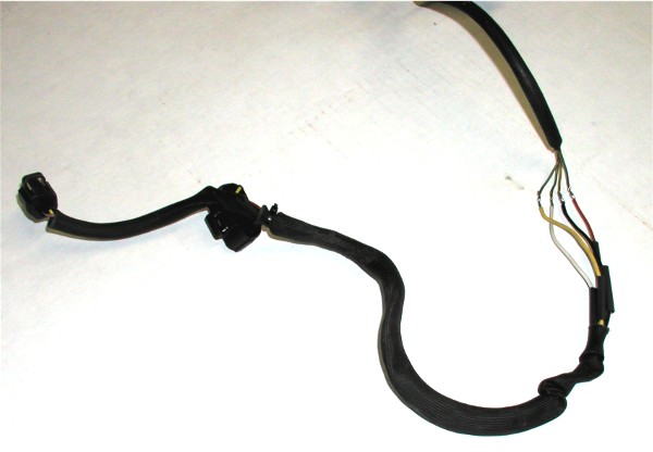 Step #2 "Attached Wires"Here we have the new connections soldered and shrunk wrapped. Then we slide the thermal sleeve back down and over the connections for a clean and factory appearing installation. 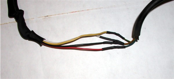 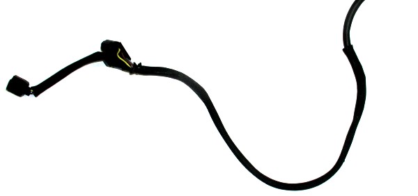 Step #3 "New Power Supply for MAF Meter"The blue wire at this meter connection was the 5 volt power supply for the old Air Flow Meter. The new MAF meter must have 12 volt switched power and will not operate on 5 volts. In November of 2007, we have changed our instructions for supplying this 12 volts to the MAF meter. Here we are connecting into the DME plug. If you need to access the plug and verify wires, you can see how this is done HERE. We are going to use the same blue wire that the AFM used although we need to send 12v up the wire. To do this, we need to cut the blue wire off DME pin # 9 and attach it into DME pin #18's wire (red/yellow stripe). In this pictures you will see we are also attaching the power wire for the Piggy Back Fuel controller to this power wire (#18) along with the MAF Harness power wire. Accomplishing two jobs at the same time since if installing a Piggy Back, you will need to power it. Here you see us cut the blue wire from DME pin # 9. We also strip some of the shielding off the DME pin #18 red/yellow wire allowing us to solder to it. We use a knife to accomplish this. 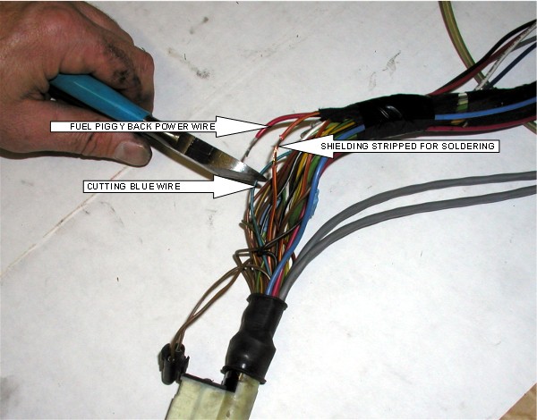 Step #4 "Soldered Connection at DME"Shown are both the piggy back power wire and the blue wire attached to the red/yellow #18 wire. Wrap this connection with electrical tape when finished to insulate it. 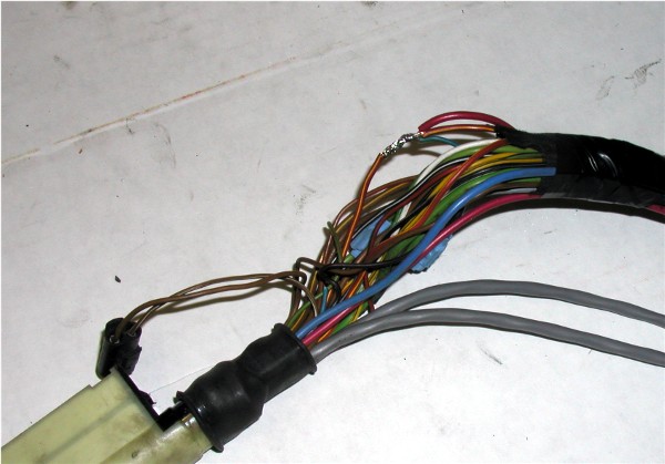
|
Secure Checkout