INJECTOR HARNESS INSTALL 944TIn the following instruction, we are installing a Replacement Fuel Injector Harness with the optional knock sensor plug into the 944 Turbo. This factory wiring harness happens to be out of the car. Many of you would be installing this injector harness with the factory wiring harness still in the car. All steps would be the same. You just do your work under the hood, and under the dash. It is not necessary to remove the factory harness and we advise against it unless you're pulling the engine at the same time.If you need help finding the DME and KLR, and need help locating connectors, refer to the DME & KLR Chip Install. instructions. This will show you where they are and how to access them. Step #1 "Position & Placement of Harness"Lay out and position the new injector harness so that the overall length is the same as the factory harness so that it reaches injector 'one' (front injector) comfortably. 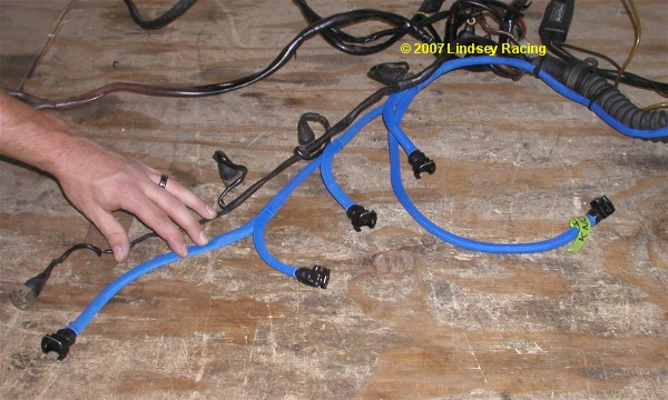 Step #2"Through the Firewall"You will need to pass the new injector harness through the firewall into the car. A good location to do this is through the large rubber firewall boot/seal. You can poke a hole through it with a small Phillips screwdriver, then use a knife to make a "+" type cut. Just large enough to allow you to push the wires through. It may work better to pull the wires through by taping onto a coat hanger wire or screwdriver from the foot well side of the boot. 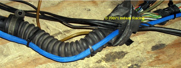 Step #3 "Disassemble DME Plug"Remove the small straight blade screw on the end of the DME plug. Roll back or slide the Rubber Boot on the opposite end. 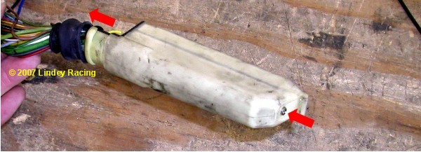 Step #4 "Slide DME Connector Cover Off"Just like it says. Slide the cover off as shown. 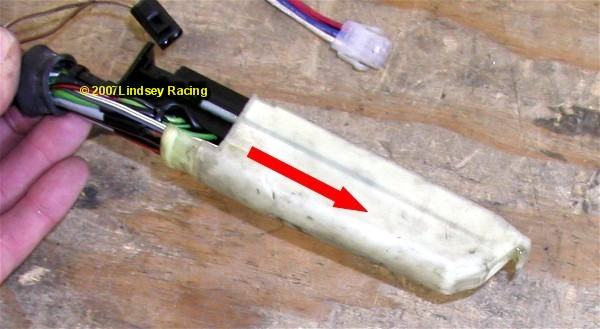 Step #5"Locate DME Pin Numbers"The DME pin numbers are located down both sides of the DME plug. On this side you see the numbers 1 thru 18, on the other side is 19 thru 36. We will be working with wires at pin numbers 14 and 15. 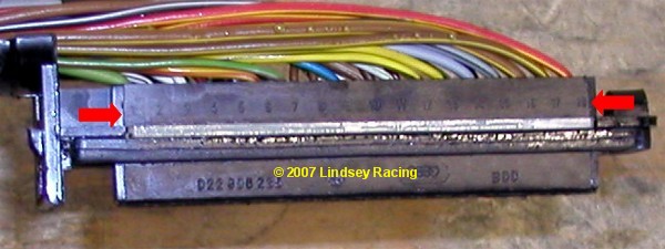 Step #6 "Remove Pin Retaining Rail"Simply remove this light green colored pin retaining rail. This keeps the pins locked into place. Without removing this, you cannot remove the original wires which is the next step. 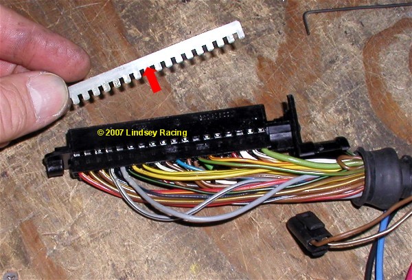 Step #7 "Remove Wires Pin 14 & 15.If you study the new wire terminal on the new injector harness, you will notice a small tang or tab that springs out of the side of the terminal that works like a fish hook. This must be depressed in order to remove the old pin/wire from the DME plug. There is a small square area or access point on the side of the terminal pin. If you slide a small object down this hole such as a small Allen wrench, small screwdriver (like the one you get in a eye glass repair kit) or even a heavy paper clip, you can depress this tab. Once depressed, you can simply pull the wire out from the other side. This is the hardest part of the job. They can be a little stubborn. You might try pushing the wire in tight, at the same time you trying to depress the tab. Then pull on the wire. Once you get the first one out, the second will probably take you seconds. There is actually a tool for this, but most people have something around the house or tool box that will work. 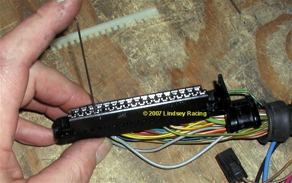 Step #8 "Replace Pin Wires 14 & 15Double check to verify you removed 14 and 15. You can now clip/cut and remove the old wires 14 and 15. Here we are using a pair of needle nose pliers to spread the rubber boot enabling us to slide the new wires through the boot. Next we re-install the new wires. Orient the pin terminal so that the spring tab or tang is like the original was. This would be so that it went into the access hole side. Plug the new BLUE harness wire into DME pin #14 slot, and the new RED harness wire into DME pin #15 slot. 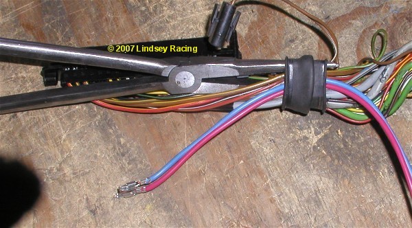 Step #9 "Close Connector Up"Re-install the Pin Retaining Rail you removed in step 6. Slide the DME connector cover back into place. Re-install the small end screw. Slide or roll the rubber boot back into place. The DME Connector is now complete. 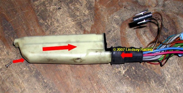 Step #10 "KLR Plug"The KLR plug is very similar to the DME plug. Remove the small Phillips screw shown here. Peel back or roll back the rubber boot. 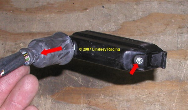 Step #11 "Remove Rubber Seal"Remove the rubber seal or gasket. A small screwdriver or pick works good to hook and pull on it. 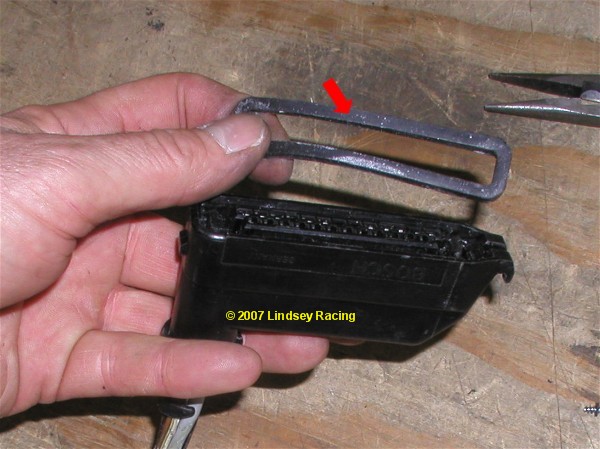 Step #12 "Pulling Pin Holder"The end opposite the small screw has a hook or shoulder in the plug not allowing you to pull it straight out. Pull on the small screw end and it will tilt and swing out. 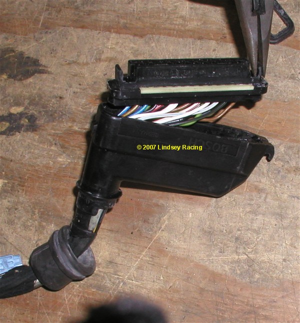 Step #13 "Identify Pins"Here, like the DME, we show the location of the pin numbers. If you were just installing the Injector Harness, without the Knock Sensor option, or the Knock Sensor Harness separately, then it would not be necessary to disassemble the KLR plug. The black wire on the Injector Harness "T"s into the large black wire with yellow stripe. It's always a good idea to verify it though. Since on this illustration we are installing the Knock Sensor Option, we needed to disassemble the plug. 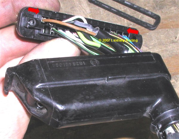 Step #14 "Remove Pin Retaining Rail.Simply pull the pin retaining rail out. 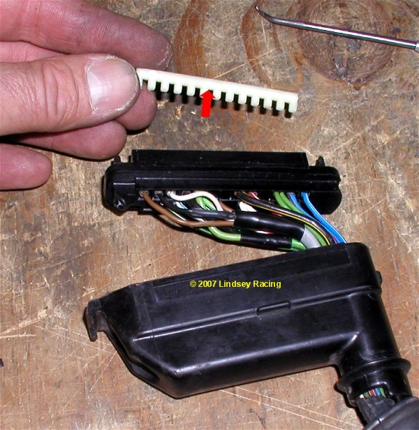 Step #15 "Remove Old Knock Sensor Wires"We need to remove the old knock sensor wires from the KLR plug for pin numbers 11, 12 and 13. 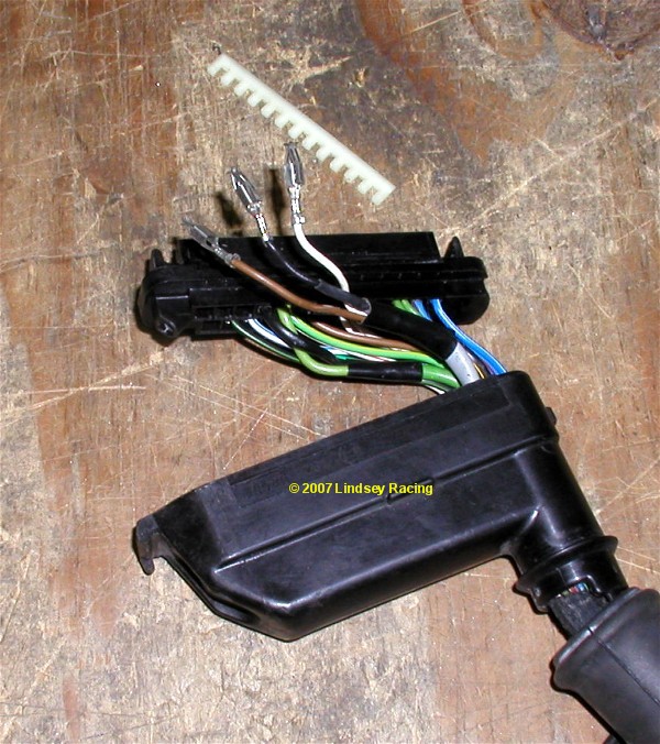 Step #16 "Cut Wires"Here you see us cut the gray cable that contains those three wires you just un-plugged from the KLR plug. We do this because it gets a little crowded trying to fish new wires into the plug without removing the old first. 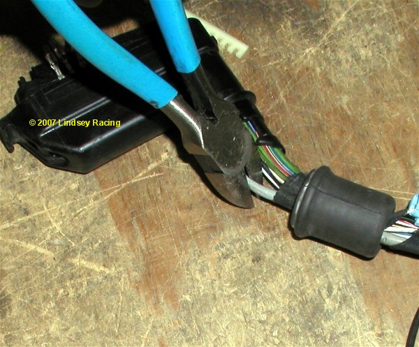 Step #17 "Install New Wires"Like with the DME plug, fish the wires through the rubber boot and into the plug. Install the new wires into the KLR connector as follows. Make sure once again that you have the terminal orientated correctly so that the spring tab locks or snaps into place. Pin 11 = Black Covered Wire Pin 12 = Bare Ground Wires Pin 13 = Clear Covered Wire 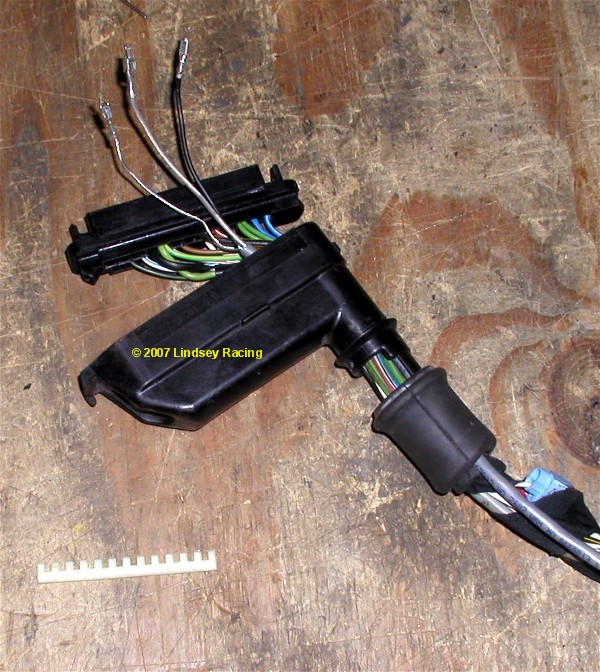 Step #18 "Complete KLR Plug"Re-install the terminal pin retaining rail. Then re-install the terminal holder into the plug housing. You need to install the end opposite the small screw first, then rotate the other end down and in. There is a tap that the terminal holder goes underneath. If it's not correct, then the terminal holder will not fully seat and it will not be parallel to the plug housing surface. Re-install the small Phillips screws. 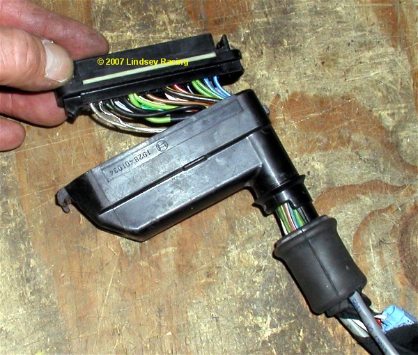 Step #19 "Prep for Soldering"On the Injector Harness, there is the black wire that needs to "T" into the black with yellow stripe #6 wire form the KLR plug. We removed a portion of the wire covering with a knife to expose the bare inner wire. 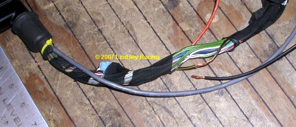 Step #20 "Solder Connection"Here you see the solder joint. You need to wrap and protect this connection with electrical tape once soldered. 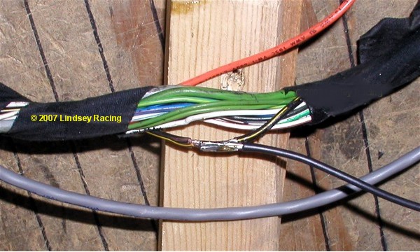 Step #21 "Terminate Old Injector Harness"Using a pair of side cutters, we cut off the old injector harness from the main engine harness a few inches from where it protrudes from the larger mass of wires. There are four red wires in this group of wires. We then cut trim these four wires so they end at different lengths. Then tape this connection using electrical tape to protect it from touching anything metal or grounding since these red wires are hot (12v power). 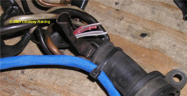
|
Secure Checkout