STOCK REPLACEMENT FUEL LINE INSTALLStep by Step instructions for installing the Lindsey Racing Stock Replacement fuel lines that enter through the right strut tower opening on your 944 and 951.ALWAYS USE CAUTION WHEN WORKING WITH FUEL. NO SMOKING, OPEN FLAME OR SPARKS SHOULD BE PRESENT. WORK IN WELL VENTILATED WORK AREA. Step #1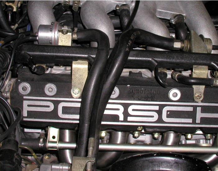 These are the stock fuel lines we are about the replace on a 944 Turbo. Late 944s, where the fuel line enters through the shock tower, are essentially the same. For future reference, the front line (right on picture) is the high pressure fuel feed line to the fuel rail. The rear line, (left in picture) is the low pressure return line back to the gas tank. The feed line is 10mm in diameter where rubber lines change to steel, and the return is 8mm. We will refer to these during the installation so it's best to familiarize yourself with them. Step #2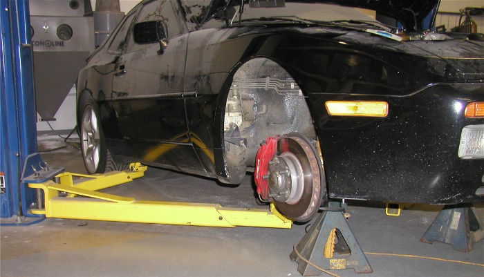 We need the front of the car raised up and the rear of the car down. We do this so, when we cut the fuel lines, you will not have fuel continually running out of the lines onto the floor, which would be a fire danger. Although we do not show pictures for the procedure, you will need to remove the right front wheel and the plastic inner fender from the car. There are several bolts located around the inner fender to attach it. Remove all bolts. Curl the ends of the inner fender and roll out to remove it. Although the inner fender keeps the fuel lines fairly clean behind it, before we start marking and cutting lines, wipe the lines down with a solvent rag. This will help eliminate any dirt or debris from getting into our fuel lines and clogging a fuel injector. If you can blow the area down with a air gun, that is also wise to do before proceeding. Step #3 Here you see the 10mm feed line (right) and the 8mm return line (left) view from the wheel opening with the plastic inner fender removed. Step #4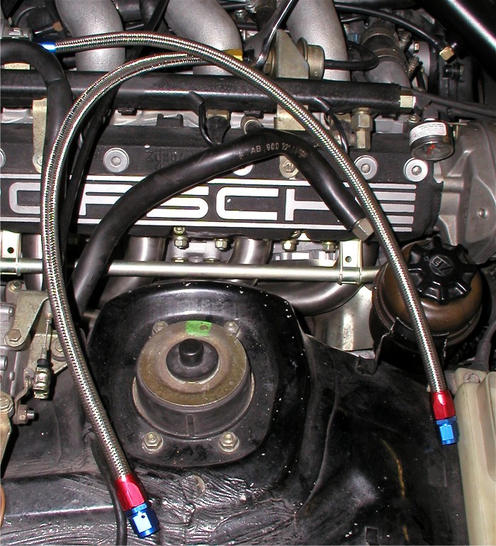 Disconnect the factory fuel lines at the fuel damper and fuel regulator and move them slightly aside. Then attach the new replacement lines at the fuel damper and regulator. INSTALL TIP: Apply a couple of drops of motor oil to the thread on the fuel damper before installing the replacement hose. The lines have the same fittings and connections as the lines you are removing. Step #5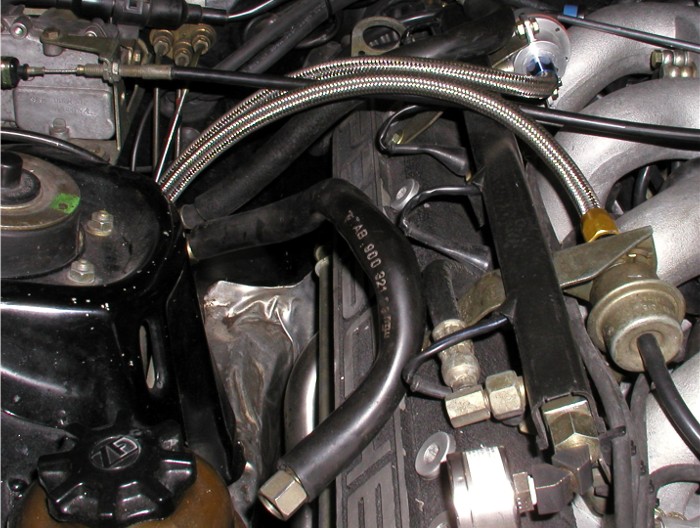 IMPORTANT SAFETY INFORMATION: This picture shows you the position or amount of drape or curve of the fuel lines we are trying to achieve. The fuel lines need to have this to allow engine to move and torque without damaging the lines or pulling on the fuel rail. More drape is better then not enough. If inadequate drape is used, it could result in a fuel leak and/or fire. Whether installing our stock replacement lines on a stock rail, or installing a Lindsey Racing fuel rail with line kits, always take precaution in insuring that you allow enough drape for engine torque and braking and cornering forces when the engine can move around. Step #6 Temporarily install (hand tighten) the supplied compression fittings on to the new replacement lines. The 10mm compression fitting on the 10mm (front) feed line, and the 8mm compression fitting on the 8mm (rear) return line. You can look at the compression fitting and determine which is the 10mm and 8mm by visual size comparison. The opposite end of the fitting is the same. With the proper amount of drape of the fuel lines under the hood, position the fitting against the appropriate steel fuel lines and mark the line flush with the end of the fitting. This will be where you make your cut using the tubing cutter. Step #7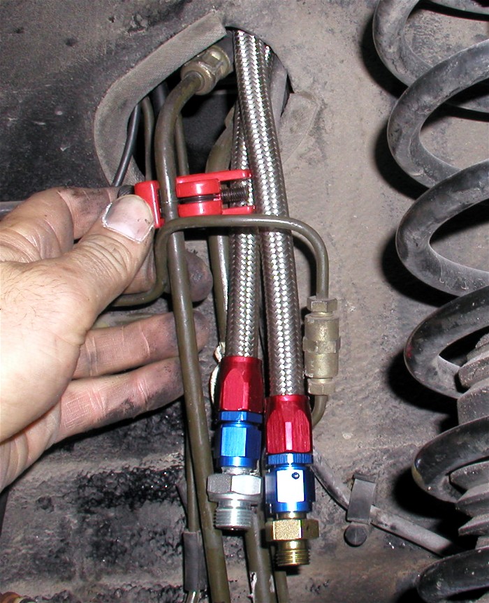 On this particular car, it has ABS which means it has many more brake lines around the fuel lines. Some of these make the job difficult. The mark to cut the lines is actually further down the steel tube. Here we are cutting the lines near where the brake line crosses over the fuel line to allow us to then swing the fuel line out from behind the brake line to make it easier to make your cut down low at the actual marked spot. Step #8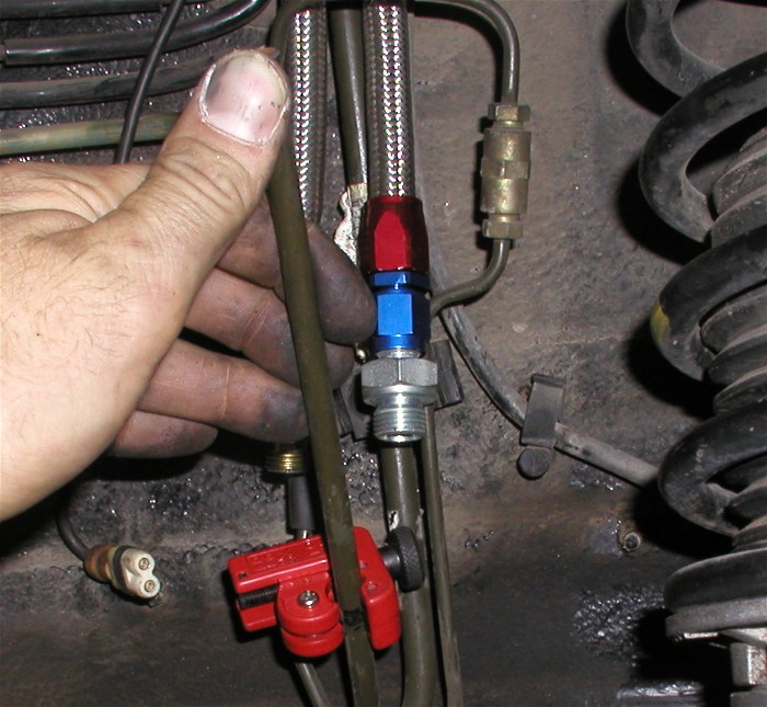 Here we are making the final cut at the marked spot on the return fuel line. You can rotate or lean the fuel line out having made the upper cut first making it easier to rotate the tubing cutter when performing the lower final cut. If the line is still leaning out after the final cut, using your hands, bend the line back vertical again. You can do this by supporting the line at the base where it's bent with one hand from pushing back, then pushing in/back on the top or cut point on the line. Step #9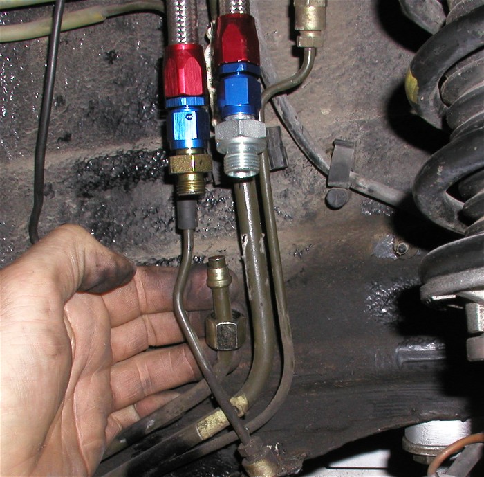 Here we have slipped the 8mm compression nut down the 8mm fuel line. Then slide down the "bit sleeve" in this orientation. Fat end down! We want to see steel line protruding out the bite sleeve as pictured. Step #10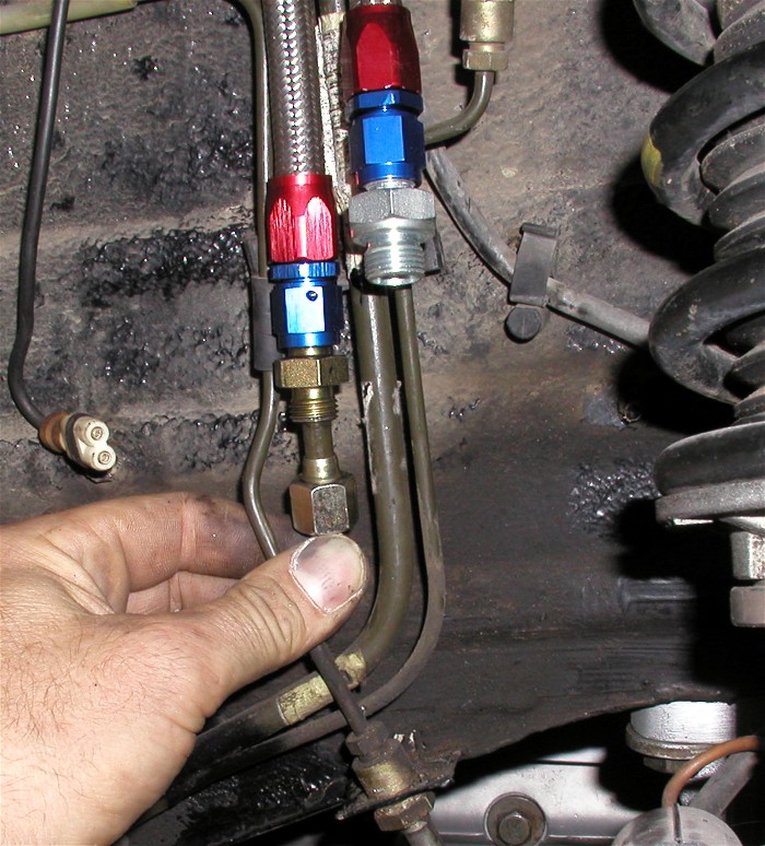 Although we could not accurately show it, because one hand was holding the camera, hold the compression fitting that is attached to the new fuel line down against the new cut off 8mm steel line. The steel line should be going up inside the compression fitting about 10mm. Then while holding down, applying pressure to keep the tube in the fitting, slide the compression nut upward to the compression fitting. The bite sleeve should slide into it's final position on it's own. Hand tighten the nut as tight as you can. We want to make sure the tube does not slide back out, compromising the connection. Step #11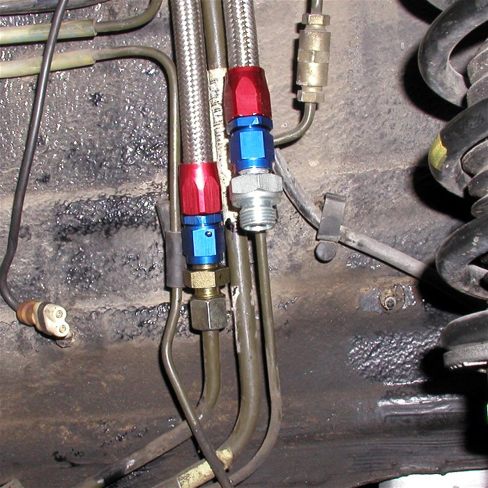 What it should look like once installed. Step #12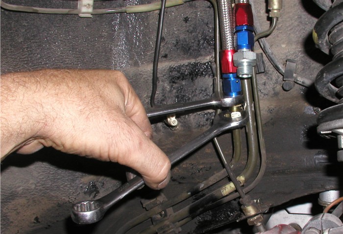 Having made sure the steel fuel line has not slid down from inside the fitting, do a final tighten of this connection. Step #13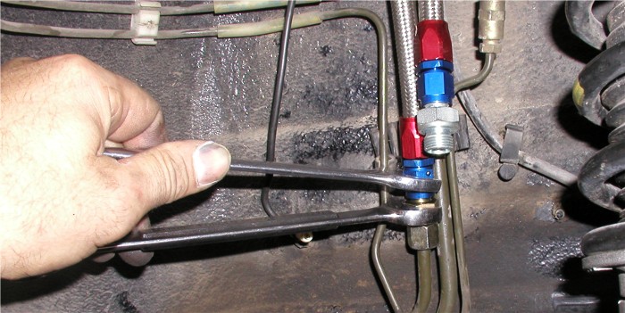 Final tighten the fuel lines end fitting (blue in this picture) to the compression fitting. Step #14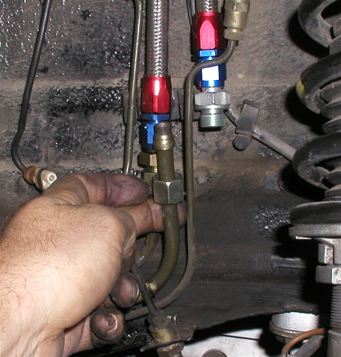 Here you see we have cut the 10mm steel line at our mark, and installed the 10 compression nut and 10mm bite sleeve as we did with the 8mm return line. Same process on this line. Step #15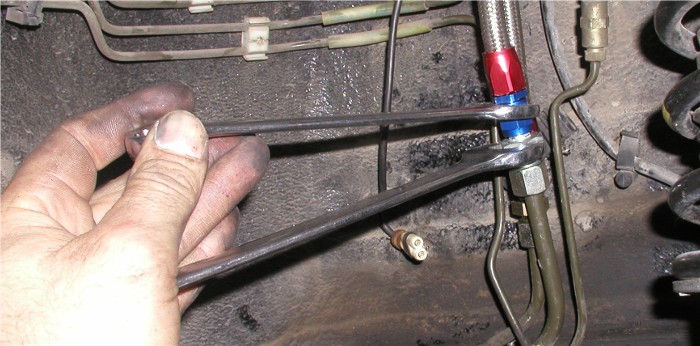 Final tighten the compression nut to the compression fitting. Final tighten the fuel lines end fitting (blue in this picture) to the compression fitting. Step #16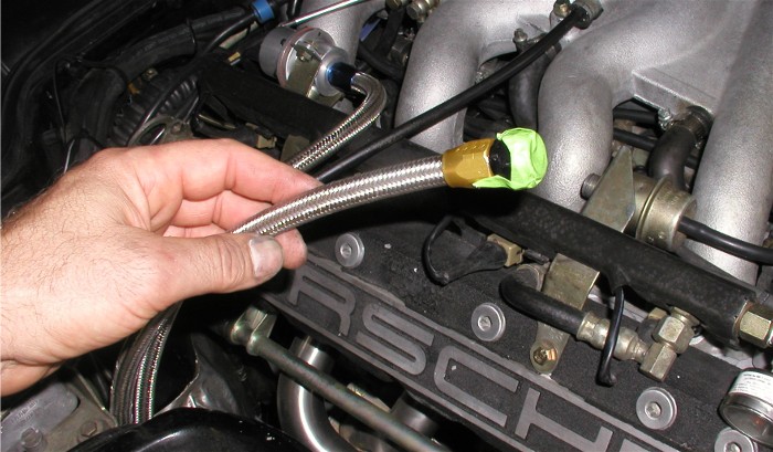 On this installation, we are going to install the optional Thermal Sleeving on the fuel lines. Since the sleeving is fiber lined, we are concerned about these fibers getting into the fuel lines when sliding the sleeving over the fuel lines. So we put a piece of tape temporarily over the end of the line to seal it. This will insure we don't clog a fuel injector. We cut the 36" roll of sleeving in half and installed a piece on each fuel line. Whether you install the sleeving or not, now is the time to final tighten the fuel lines at the fuel regulator and fuel damper connections on the fuel rail. Step #17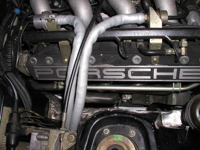 Here is the final product. New fuel lines with thermal sleeving protecting them from the heat. Secure the fuel lines to the chassis near the compression fittings using the supplied replacement plastic clamp or use wire ties. Re-install the inner fender liner and replace the wheel. Torque wheel to 95 ft. pounds. |
Secure Checkout