REPLACING DME & KLR CHIP IN 944TNOTE: A DME Chip in any Naturally Aspirated 924S, 944 from '85/2 would be the same process shown here only you're only changing a DME Chip since there is no KLR on the rack.Replacing the chip set in the 944 Turbo is typically the first modification anyone does. It's not necessary to take the car to a mechanic to perform this switch. We feel it's pretty straight forward and can be performed by anyone. *** DISCONNECT THE GROUND TERMINAL ON THE BATTERY BEFORE PROCEEDING *** Step #1 "Locate DME / KLR & Remove Foot Board"The DME/KLR Rack is located under the passenger's feet. The carpet is attached at the top with Velcro. Pull or peel the carpet back to expose the protective foot board. The foot board has four #2 Philips screws holding it in place. Remove all four screws and accompanying washers and remove the foot board. 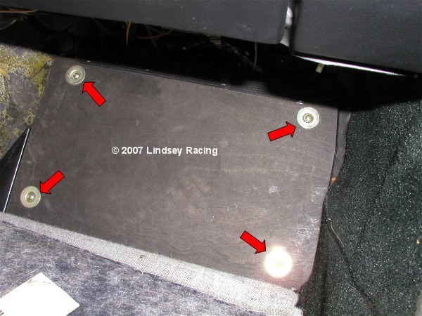 Step #2 "Remove DME / KLR Rack"There are two #2 Philips screw at the bottom of the rack and two plastic screws at the top that can be removed with a straight blade screwdriver. Remove all 4 pieces and pull out the rack. It works best to pull from the bottom. 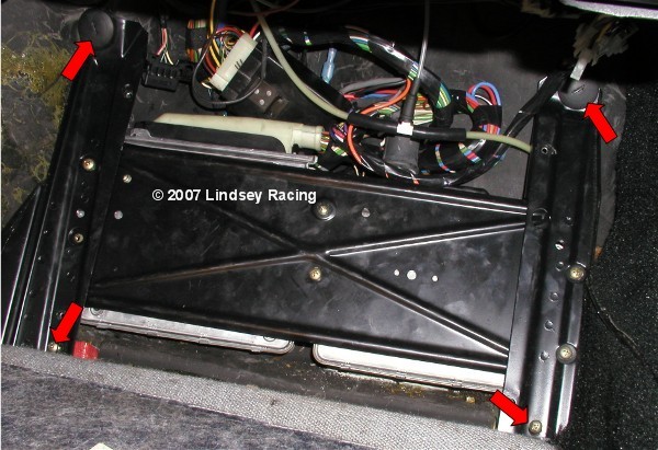 Step #3 "Un-plug DME & KLR"There is a locking spring tab on the wire outlet end of both the DME and KLR plug. Pry away from the plug using your finger or a screwdriver. 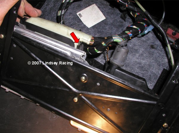 Step #4 "Rotate Plug Connector Out"While holding out the spring tab, rotate out the plug. This is done the same way on both the DME and KLR. You will also need to disconnect the KLR hose/tube from the KLR. There is a small knurled thumb collar at the KLR. Un-screw this collar from the fitting. Once you pull the collar back away from the fitting, carefully pull the hose off the fitting's nipple. In these pictures, the KLR line is cut as we have connected in a boost gauge and "T"ed it in at this point. 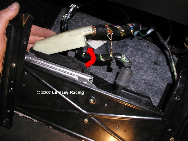 Step #5 "Orientation & Identification"The DME and KLR are pictured here on their rack. The DME (right) is larger than the KLR (left). This view may come in handy later when re-installing them back on the rack. 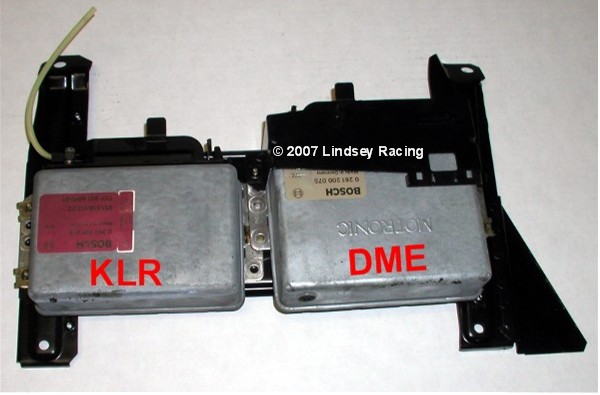 \ Step #6 "Remove DME & KLR From Rack"You may choose to remove one at a time to change the chip, or both together. Remove the Phillips screws attaching them to the rack. 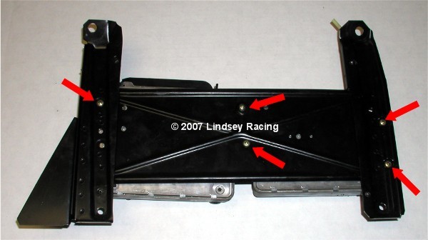 Step #7 "Prepare To Remove Cover"Lay the DME on it's back to expose the cover tabs. 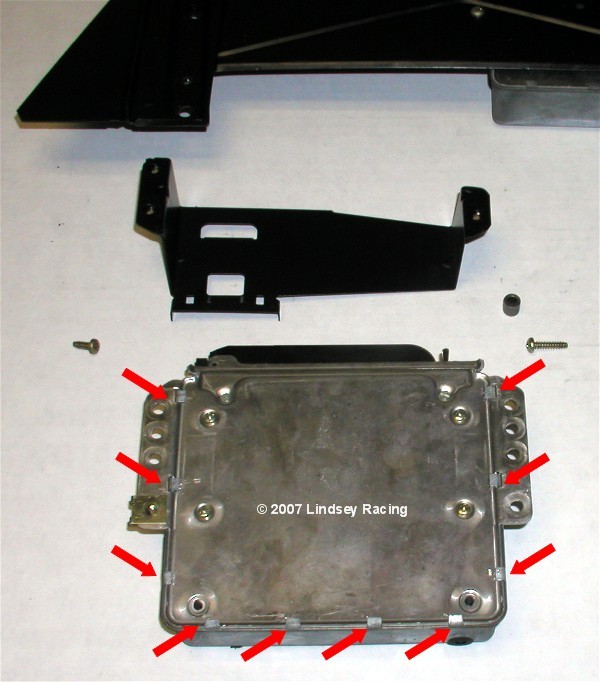 Step #8 "Bending Tabs For Cover Removal"With a straight blade screwdriver, get underneath the tabs and pry or bend them up at 90 degrees to the DME back.  Step #9 "Remove DME Cover"Once the tabs are all bent up, simply remove the cover and plastic insulator sheet. 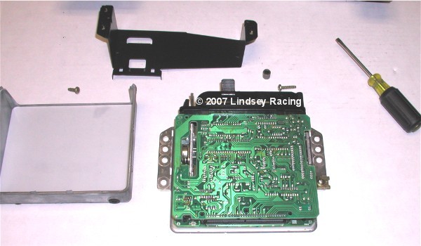 Step #10 "Separate The Board"We find the easiest way to separate the board is to "pop" it up with your thumbs. While holding down on the bottom or back with your fingers, gently press up on the top board with your thumbs. The board posts will separate with a "pop". If your chip has never been changed, it may be stiff so go slow and easy. Don't over extend or press too far with your thumbs. In other words, when pressing, anticipate limiting the movement of your thumb so you don't overdo it. 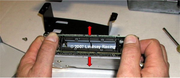 Step #11 "Separated Board"Here you see the board posts separated. 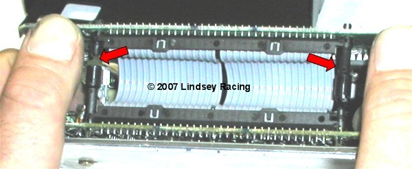 Step #12 "Slide Out Board"While holding down the DME, and the ribbon side of the board released from the posts (board should be at a angle now) slip or slide the board out of the plug or connector end. 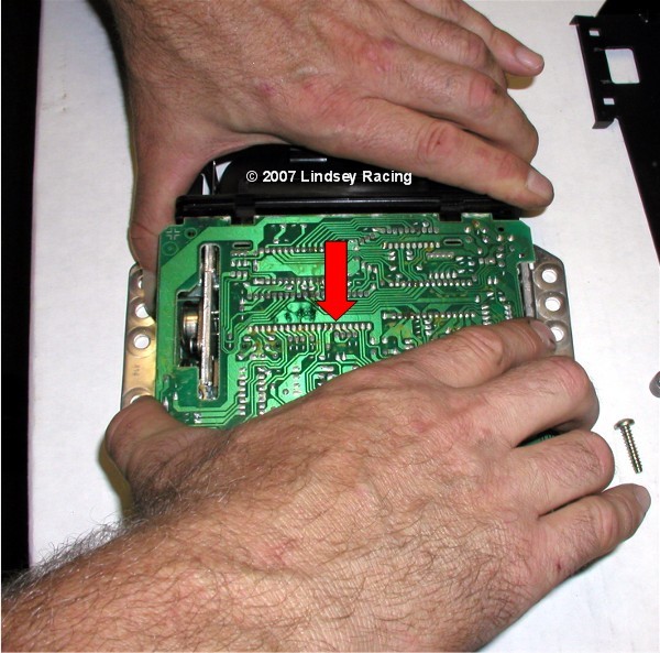 Step #13 "Flip Open"After you slip out the end, you can simply lay the top board back open, exposing the DME chip. 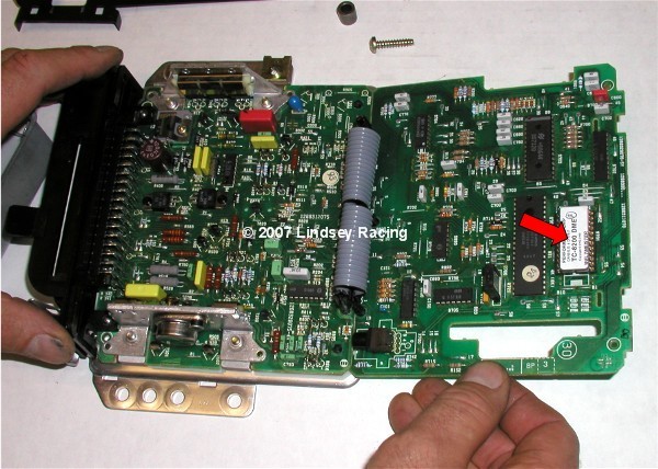 Step #14 "Remove DME Chip"With a straight blade screwdriver, slip the tip under the end of the chip between the chip and the chip socket. Gently rotate the screw driver counter clockwise then clockwise about 1/8 turn back and forth. Continue to slip the screw driver in further and further as you continue to rotate the screwdriver. 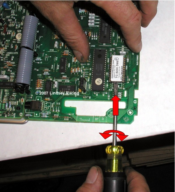 Step #15 "Empty Socket"The DME chips socket is now ready for the new DME chip. 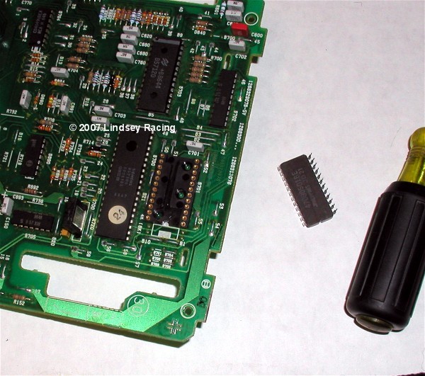 Step #16 "Orient & Position DME Chip"The DME chip has a "notch" on one end. The socket that the DME chip plugs into also has a "notch". These need to be aligned notch above notch. Make sure the chips pins are aligned with all the holes in the socket. 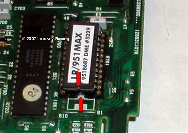 Step #17 "Press in DME Chip"Slowly and gently press the chip into the socket. Once in, view the pins to make sure they all went into the sockets and not bent outward and missed. 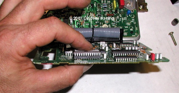 Step #18 "Insert Board In Plug"With the board tilted, slip the board end back into the plug end of the DME. 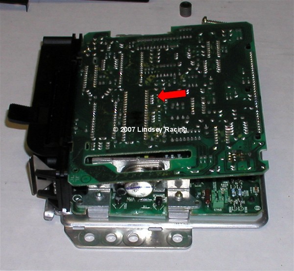 Step #19 "Snap Together"With the end into the plug, press down on the top board ribbon cable end and it will "snap" back together on the posts. 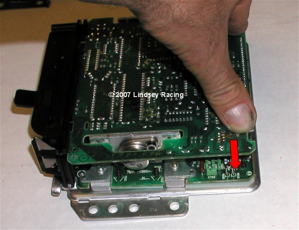 Step #20 "Close Tabs"With the cover and white plastic insulator back in place, use the screwdriver and fold the tabs back over to their original position. If you think you might be back in here at some point in the future, you may only want to bend over a couple of the tabs. When you fold them back and forth over and over, they tend to break off. 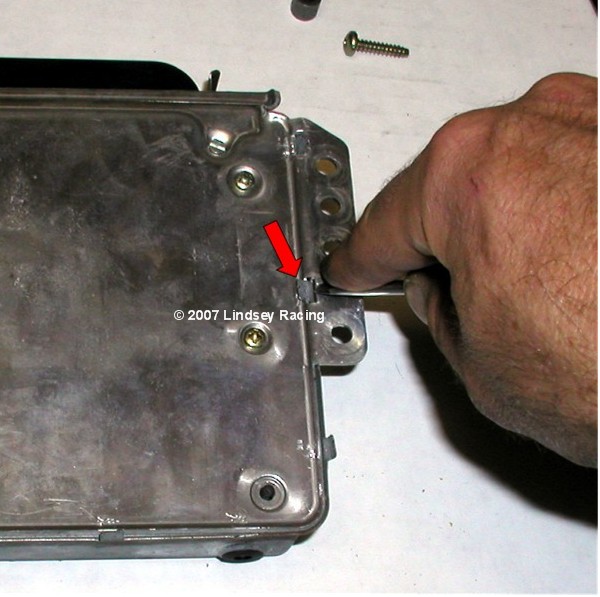 Step #21 "KLR Board Opening"Remove the KLR from the rack if you haven't already. Remove the cover and plastic insulator as you did on the DME by bending back the tabs. On the KLR, it may (usually does) have another device holding the boards together in addition to the posts as with the DME. There is a pin passing through the boards and locking into place with the "jaw" on the top board. Locate this and press the pin down on the end with the screwdriver. 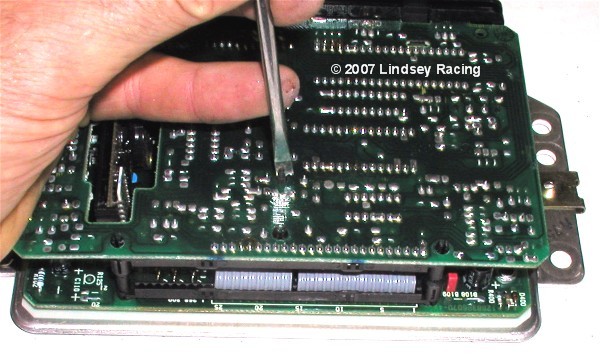 Step #22 "Pull Pin"Flip the KLR over and locate the pin. Pull it a little further out to about what you see in this picture and leave there. 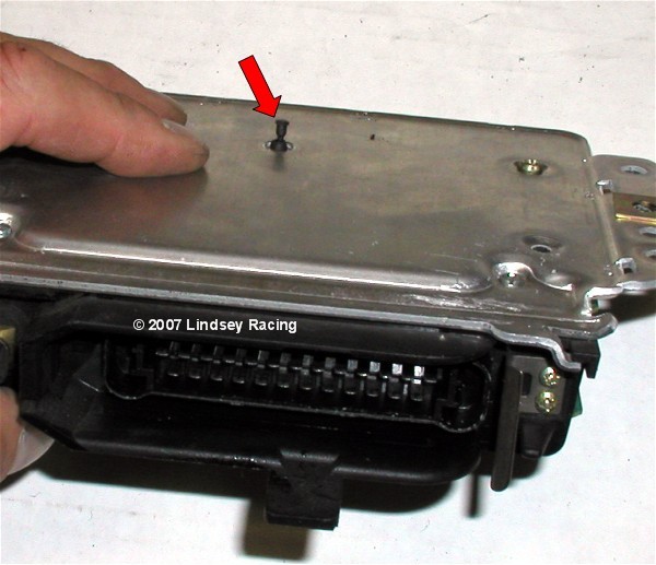 Step #23 "Snap Board Apart & Lay Open"Just like the DME, using your finger and thumbs, pop apart the ribbon cable end of the KLR boards. Then lay the top board back to open and expose the KLR chip. 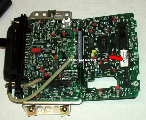 Step #24 "Orient KLR Chip With Socket"Like the DME, we need to align the notches on the KLR chip and chip socket. Once aligned, place the KLR chip into the socket and make sure all the pins are aligned with the pin sockets. 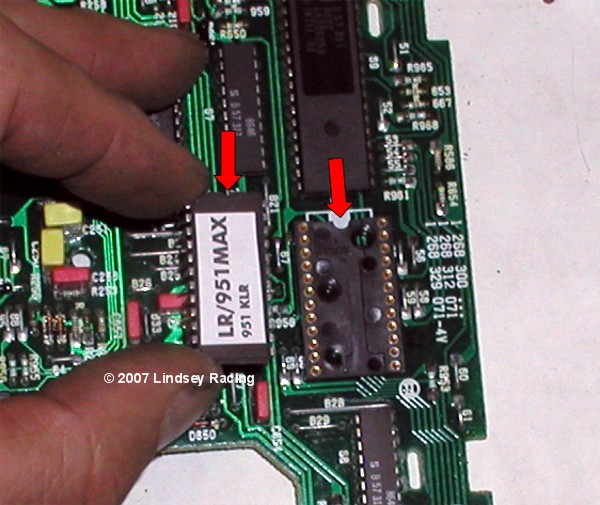 Step #25 "Press In KLR Chip"Gently press the KLR chip into the socket. 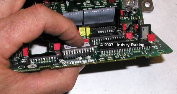 Step #26 "Slide Board Into Plug End"With the board tilted, slip the board back into the plug end of the KLR. 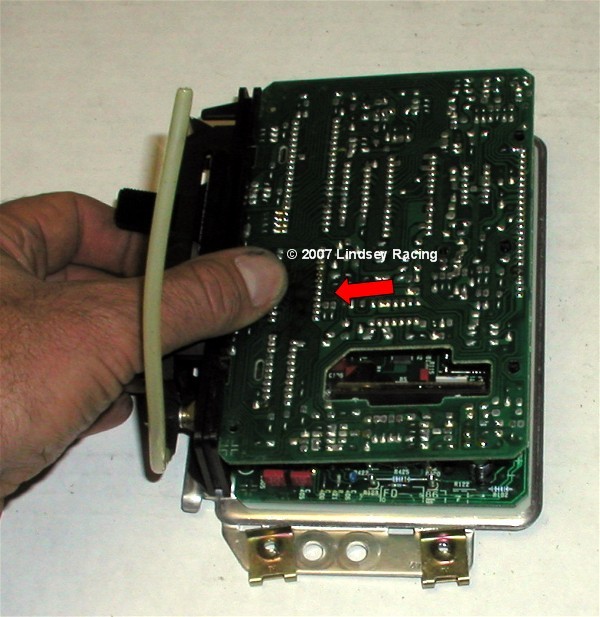 Step #27 "Press Board Together"Press the ribbon cable end of the board back together until the board posts snap together like they did with the DME. 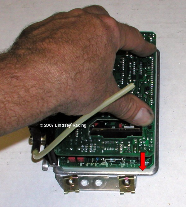 Step #28 "Press in PinPress the pin back into the boards. 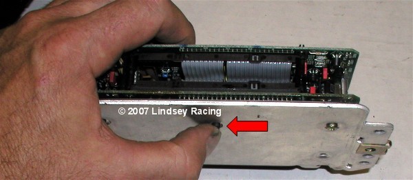 Step #29 "Mount DME & KLR On Rack."Attach the DME and KLR back onto tie rack using the Phillips screws. Step 30 "Install DME & KLR Plugs"The DME and KLR plug have a lip or tab on the end opposite the wires that needs to slip under and into a mating hole. Slide the plug into the DME with it tipped up, then rotate down and snap into place making sure the spring tab has secured and locked down the plug. 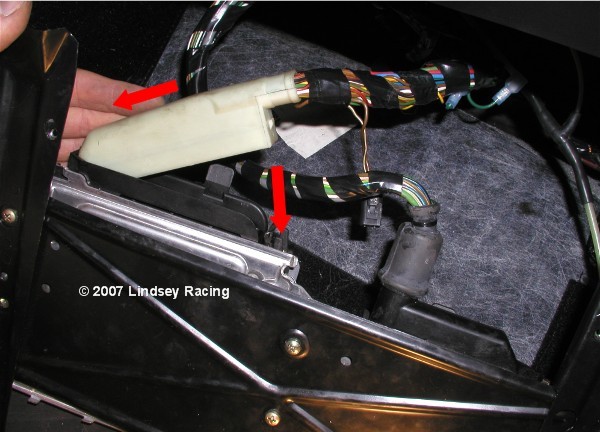 Step 31 "Install DME & KLR Rack"First we need to re-connect the KLR hose. Push the hose back onto the fitting nipple and then screw down and secure the knurled collar. In the case of this car, you see the "T" where we have tied in the boost gauge. Make sure that you position things so that the vacuum hose connectors do not fold over or pinch off the vacuum hoses when putting the foot board back on. This could cause a loss of boost signal to the KLR and Boost Gauge which would not be good. After making sure both plugs are seated correctly, and the KLR hose it connected, place the DME / KLR rack back into the floor. Secure with the 4 fasteners that you removed earlier. Step 32 "Install Foot Board"After looking to make sure all wires are in place and not pinched, and that the KLR line is not kinked in any way, then re-position the foot board on the DME & KLR rack. Re-Install the 4 screws and washers and tighten. Replace carpet.
|
Secure Checkout