|
OCTOBER NEWS
A case of Sibling Rivalry... For the past few days, knowing the news letter needs to go out , I have been trying to figure out what to use as the "cover" shot. I thought maybe a picture from the parts rooms, the packaging areas or perhaps the shop somewhere. Even this morning, September 30th, I still hadn't decided what to shoot and I knew time was running out. I drove my red 89 Turbo S in today and parked it by the side of the building. Wes and I went out in the country and were doing some fine tuning on my white 88 Turbo S with our new LR/951MAX Chip set. When we returned, I parked the 88 close to the 89 not thinking much of it. Then later when it came time to call it a day, I walked outside and looked at the two cars sitting side by side. I stood there for a minute or two asking myself which car should I take home for the weekend. I realized this was a delemma I haven't faced before. I recently purchased the 89S and never had both cars at the shop at the same time before without anything else to drive home. Do I take the younger almost stock (278 RWHP) Beautiful Guards Red 89 S or it's older sibling the Sporty Alpine White 88S with 500 RWHP. Well... you will just have to guess how it turned out. Then the proverbial "light bulb" came on and I snapped a couple of pictures of the brothers.
OCTOBER SPECIALSFor the Month of October, we will be offering the following specials. This special pricing is for our retail customers only. Other discounts and programs do not apply and cannot be combined. You must request the special pricing at time of ordering. The shopping cart does not recognize our specials and will NOT automatically give you the special pricing. You MUST either send us a follow up e-mail immediately after ordering through the shopping cart or International Order Form, or give us a telephone call and ask for your special pricing. If you order by phone, you MUST mention the special pricing at time of order. If you contact us after the order is shipped and request the special pricing, it will be too late to receive it.The Lindsey Racing Stage V Header Panel is 15% off regular price this October. This aggressive looking panel is both functional and unique. It's offered in two versions allowing you to either retain the factory pop-up headlights, or remove them completely.
The Battery Cut-Off switch is being introduced for $169.95. This product is way over due for the racing scene. No more hard to mount pull cables.
The Lindsey Racing Gauge Panel is 25% off this month. This very popular gauge and boost controller mount locates under the factory radio.
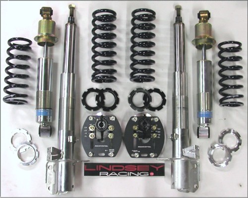
Our already low pricing on the Bilstein Escort Suspension Kit is even better this October with 10% off regular price while supplies last. Available with or without adjustable camber plates, and configured in both street/track or dedicated track valving.
CUSTOMER CAR OF THE MONTHWould you like to be featured as car of the month? Please submit pictures and information to Dave Lindsey.
Theo Schultz is the proud owner of this beautiful 951. He is employed at
Yarrow Sport LLC in Providence Road Island.
It boasts a 2.8 Liter engine with a cross drilled 3 liter crankshaft, Pauter connecting rods and Mahle
2.8L stroker pistons. Sitting atop the block is a Lindsey Racing prepared
cylinder head with ported intake port, hi-velocity exhaust and a solid
lifter camshaft package with a Web Cam camshaft custom made for Lindsey
Racing. Also included is a Lindsey Intake Manifold, Lindsey Stage V
Intercooler, Lindsey Super 75 T4 Turbo, SPEC Clutch Kit, Hard Pipe, BOV, Coolant Bottle,
Turbo Filter, Bilstein Escort Suspension, Big Red Brakes and a host of other Lindsey
Racing products. The car is currently being equipped with a Tech 3R engine
management system.
Theo�s car will be street driven as well as track, plus it will make the
local car shows in the area. The beautiful paint job and attention to
detail will assure Theo of many trophies.
The reason to degree in your camshaft can vary. Perhaps it's a new camshaft and you want it set to the manufacturer's specifications, or you want to move your power band around a little. Both will require you
to know where it's at.
We were recently doing a solid set-up on a in-house motor for a customer. We thought we may be able to save him
the expense of the adjustable cam gear should his new cam be in the proper position with his stock gear. We simply
checked the relationship with our new Lindsey Racing Camshaft Degree Wheel Kit and discovered his cam was 5 degrees retarded. The adjustable gear was absolutely necessary in this case since the performance we were looking for required the cam in a particular position.
Just the other day, a customer was telling Mike that he assembled his engine and checked his positions and
his cam was 9 degrees off. The customer had his cylinder head milled .040" to boost compression which added to the stacking up of tolerances. You can have a number of things cause this. Keyway location in the crank gear. Keyway location in the cam gear. Belt stretch. Block deck height. Cylinder head thickness between the cam and gasket surface.
Bottom line is... you NEVER really know where you cam is until you check it.
Locating TDC (Top Dead Center):
To accurately locate TDC on the #1 cylinder, we need to bring the piston to the top of it's stroke. With the dial indicator protruding down through the #1 spark plug hole and the pointer resting on the top of the piston, we want to find the point where the piston is at it's highest point. Rotate the crankshaft slowly clockwise while watching the dial indicator. We are looking for the exact point where the dial indicator is indicating the highest position of the piston (TDC).
Positioning the Degree Wheel:
With the degree wheel installed on the mounting hub, slip it over the power steering pulley but leave the set screws loose enough to allow you to rotate the wheel. Install the pointing device to point to the degree marks on the wheel. The pointer should be attached to the engine block and not touch the degree wheel. Providing the piston is still at TDC, rotate the degree wheel until the pointer is aligned with the "0" on the degree wheel then tighten down the set screws locking it in place. If the piston had moved, then once again locate TDC and then position the wheel. Rotate the engine a couple of revolutions to make sure it comes back up TDC on the piston and "0" on the degree wheel.
Checking Cam Location:
NOTE: It's much easier to perform the next step if you have a Lindsey Racing prepared cam box with inspection ports machined down the side. These ports are there to allow you to access and measure the lash on the valves. They also make it much easier to locate the dial indicator foot on the #1 intake lifter. It's very difficult to look down the top bolt access hole and position the foot on the lifter with the dial indicator in the way. We recommend if your cam box is off the car, and you're equipped to do so, drill and tap a hole in the cam box for a pipe thread plug. You can contact us for the exact location if you like, but it's in line
with the center of the cam lobe. We are going to assume from here out that you have an access or view port.
Remove the 2nd cam box bolt cover plug and #1 intake lifter inspection port plug. Set up dial indicator with the �LR Lifter Foot�.
Adjust the position of the dial indicator so the LR Lifter Foot rests on top of the #1 intake lifter next to the cam lobe. It is important to make sure the Lifter Foot does not get under the cam lobe. That would trap
the Lifter Foot between the lifter and cam lobe and possibly scratch or damage either part. Adjust the dial indicator to read �0�.
Using a breaker bar or torque wrench, and 24mm deep socket, rotate the engine clockwise until you see the dial indicator just begin to show valve lift. The longer the bar, the more accurately and easily you can turn the engine over.
Slowly turn the engine until the dial indicator reads .050" lift. It can help to have a second person with you. One to watch the dial indicator and the other to watch the degree wheel and turn the crankshaft. You will see that once you relax the breaker bar, the degree wheel will back up 2-3 degrees so we don't want to do that
before taking our reading. Holding the tension against the cam belt, now read the degrees before TDC on the degree wheel. Turn the engine through its revolution and check this lift vs. crankshaft position 2 or 3 times to make sure you are getting an accurate reading.
Different camshaft grinds have different set up specifications. Refer to your LR cam set up sheet to determine your cam�s number of degrees BTDC. For this example, we will use the Webcam 274 cam profile. This cam has a set up dimension of 5 degrees BTDC. This means that at .050" lift on the intake valve, the crankshaft should be indicating and located at 5 degrees BTDC (Before TDC) on the degree wheel.
So on this particular cam, if your degree wheel is not on the 5 degree BTDC mark, you will need to adjust the cam gear to correct the setting. For those using the Lindsey Racing Adjustable Cam Gear, simply loosen the four bolts on the face of the cam gear. Now gently turn the engine while watching the alignment marks. Start by making small changes since one mark on the cam gear will make several degrees of change at the crank. Retighten the 4 cam gear bolts and recheck your cam position. Repeat the process until you get the correct relationship between the camshaft and crankshaft.
Checking Valve Lash on LR Solid Lifter Cams:
Once you have your cam tower box installed on your cylinder head and torqued down to our specifications, it's
necessary and imperative to do a final check on the valve lash or clearance between the back side (base circle) of the camshaft lobe and the solid lifter. Even though we pre-set all clearances on the valve train and tell you
exactly what part goes where, it is possible to install a lash cap crooked or have something out of
whack and not know it during your final assembly of the top end of your engine. This is the final check to make sure you did everything correctly.
For this, we are going to mark the cam gear for positioning reference. The later LR cam gears have small numbers already stamped on the outer edge of the gear for this reason. If you have an early gear, or your own gear, then you should mark the gear as indicated. A magic marker or paint works good.
Put a mark 5 teeth left or counter clockwise from the alignment mark (blue arrow) on the cam gear. Then count 10 more teeth and put another mark. Then 10 more, and 10 more. You end up with 4 marks 90 degrees apart from one another.
When you align these marks with the accompanying alignment mark on the distributor cap "clam" housing, you're able to check the valve lash on TWO different cam lobes. So you only need to rotate the engine to the 4 positions to
check all 8 lifters.
Once you have you cam in position, you simply slide your feeler gauge in through the access port between the lifter and the camshaft. Your trying to find the appropriate thickness gauge that will
slip between the two. This gives you the distance, or "lash" for that valve. The particular lash values your looking for come with your camshaft package. In a future issue, we will explain how you correct the
lash if incorrect. Since the kits are set-up when it leaves Lindsey Racing, you don't have to worry about it
that for a while.
FINAL THOUGHTSThe last of us are getting our Vacation out of the way. Everybody is rested and ready to enter the busy season. Were stocking up, organizing and looking forward to the 2006/2007 winter frenzy. We hope you get a chance to enjoy some of the Fall driving events as the cool autumn breeze sweeps through the Country.Until next month, we wish you many safe and quick laps. - The Lindsey Racing Crew
|
 |