
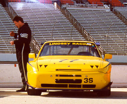
It's been a while since we displayed our updates. And believe me, we have done plenty. Here I am contemplating what to do next!
Look forward to reading about:
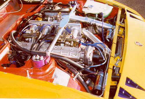
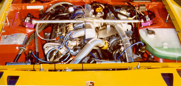
Still Updating Site - Moved the radiator back to the front of the car. We are using our Lindsey Racing Stage II Intercooler now because it cooled the intake air as well as the twin 930 part we made. This gave us the room to move things back up front.
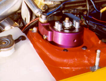
Still Updating Site - Installed the Lindsey Racing AFTERBURNER boost control system.
We also had the header and cross over pipe thermal coated both inside and out.
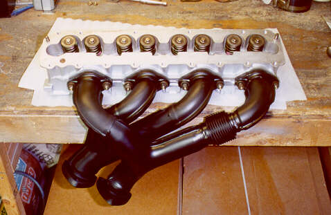
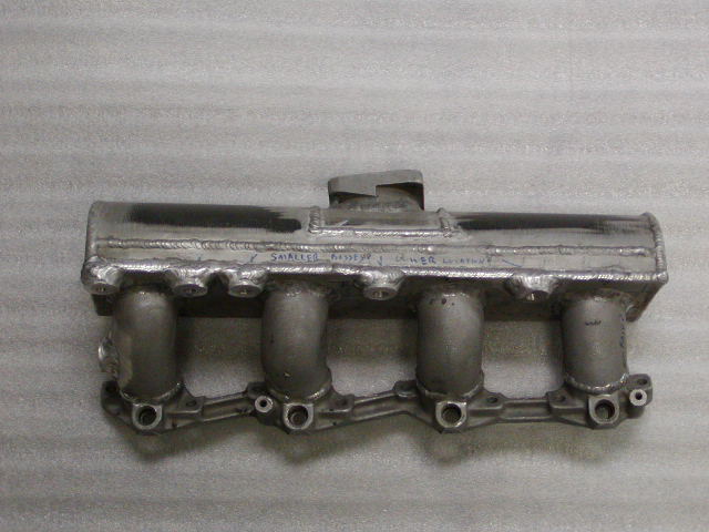
On the third prototype (pictured on the car) we had a runner cast from aluminum and thus the four runners are identical. Our research on runner length seemed to favor a 7 inch runner. In addition, the runner should be 20% larger from top to base. There are other important thing on the runner openings that our flow bench expert pointed out from his 35 years experience flowing intakes and heads. We made the back of the plenum from wood, then had a one off part cast in aluminum. From there we fabricated the front section and welded the unit together. Off to the flow bench where we got some incredible numbers. Since then we Telfon lined and thermal coated the exterior. We learned a lot building these parts. Were confident that our final design will be a piece worth waiting for.
We are in the process of producing a very similar manifold for sale. It will be a completely new part. Very similar to the part you see here with a few internal and external tweaks. We will be improving the cosmetics, the flow, and reposition some components such as the inlet a bit. It will require a new intercooler to throttle body pipe which will be part of the package. Teflon lined and thermal coated of course.
Something interesting we found out in intercooler testing is that the stock intercooler flows 5% less backwards then it does forward. Our Stage I and II intercoolers flow the same both directions after our work overs.
Look for this part to be released this Winter.
There are currently only two other intake manifolds available. The Milledge manifold for $4500. This is a very nice part but a little pricey for the average person. We expect ours to be about a quarter of the price. No carbon Fiber. Single throttle body. But capable of flowing what most any head will require. HP gains should be very similar. Maybe more. The other unit has a striking resemblence to our first prototype. Less expensive, but you get what you pay for. In addition, that system requires the reverse flow of the charge air through the intercooler. Our flow testing shows that the intercooler flows 5% less when flowing in reverse. It has to do with the restrictive cap on the inlet. Our modified intercoolers have less of a loss in reverse. Not that it matters with our intake. If you would like an intake like that, send us yours and we can chop it and tank it for about half the price. We can set it up to use the stock intercooler flow.
Still Updating Site - Installed a Kokeln Stage 5 Turbo.
Still Updating Site - Installed a Lindsey Racing MAF system with MAC II fuel controller.
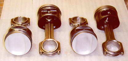
This was overdue since it had been four years since we did the last rings. We did a compression test and found that we had compression between 100 and 117. Far from where it should be. This is the compression we had when we did the 370 RWHP on the dyno. We added new rings, bearings, and installed some Pauter connecting rods. We also had the pistons coated again. The undersides were Teflon coated, the tops are thermal coated and the skirts are coated with a moly product.
Lindsey Racing NACA Duct header panel
Two products near release are the NACA Duct header panel for non headlight race cars and the NACA duct head light door covers for street cars. Fresh cold air to the Mass Air Flow and Engine compartment are the purpose. Aside from that, they look awesome as well. We can add the NACA ducts to you current fiberglass header panel. Call for info.
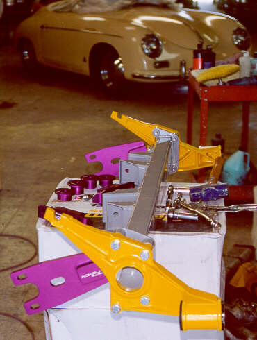
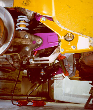
Installed Kokeln Camber Plates.
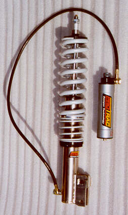
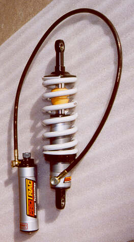
We felt that the Protrac was the best in the price range and the company offered superior customer support. Matter of fact, we liked it so much that we became a dealer for Protrac. For full information, view suspension on our site.
The springs pictured here are not the springs we ended up using. We purchased an array of Eibach springs. Because we ended up using the Kokeln raised camber plates, we used a two inch shorter spring because they supply a 2" solid spring hat that fits up inside the camber plate. The larger diameter of the spring would not allow for rotation or camber adjustment without this spring hat (extension).
On our initial setup we installed 650 lb. main springs on the front and 500 lbs. on the rear. Our research showed a 75% front/rear ratio is a good place to start. Our front and rear spring are now all 6" springs. We ordered a set of 450, 550, 600 and 700 lb. springs. We can swap the front and rear spring and raise or lower the whole set-up in 50 pound increments.
In addition, the remote reservoirs on the dampers are Nitrogen filled. They are set at time of manufacture at 12 bar (174 psi.) of pressure. You can raise or lower this pressure and in effect simulate a stiffer or weaker spring rate. This is something you cannot do on the more expensive Penske systems which was another reason we chose Protrac. We now carry a small bottle of Nitrogen and a Penske high pressure shock tool and we can adjust at the track. It's almost as easy as adjusting the pressure in you tires.
When you consider we can adjust the spring rate, have 12 compression and 16 rebound adjustments, the system is very tunable. Now we only need to figure out what to do with all this adjustment.